U.S.S. LITTLE ROCK
CLG 4 /
CG 4
MODELING DATA - Page 1
Go to MODELING DATA - Page 2
Go to MODELING DATA - Page 3
Page last updated: 15 March, 2021
MODELING DATA - Page 1
Go to MODELING DATA - Page 2
Go to MODELING DATA - Page 3
Page last updated: 15 March, 2021
| Note: The information
contained on
this page and any linked pages is intended to be used as a source of
general information that may be useful to model builders interested in
modeling
the CLG 4 version of the USS Little Rock. No guarantee is given or
implied as to the accuracy of the information furnished. Note: Some of the
photographs and drawings below are copyrighted. Please contact the Webmaster regarding permission to use these images |
| Photographs and
Drawings (Click any photo to enlarge it.) |
|||
 Photo 1-A Camden Shipyard ca. 1959 |
 Photo 1-B Philadelphia NSY ca. 1960 |
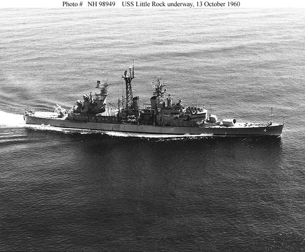 Photo 1-C Underway ca. 1960 |
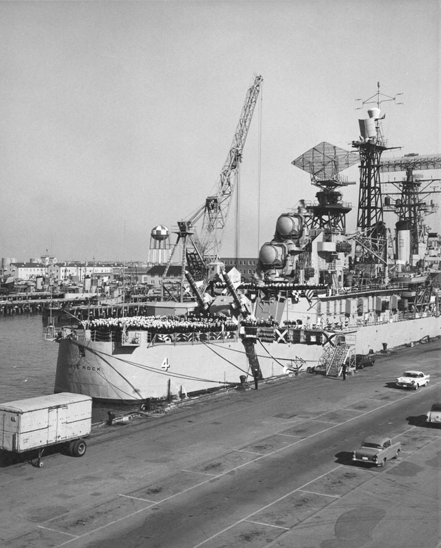 Photo 1-D Stern View 1961 |
 Photo 1-E Bow View ca. 1963 |
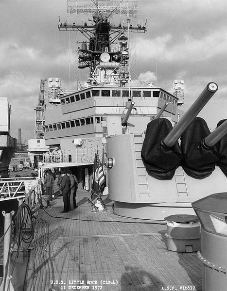 Photo 1-F 6" Turret - Boston NSY Dec. 1972 |
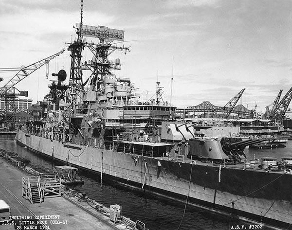 Photo 1-G Stbd Fwd Quarter - Boston ca. 1971 |
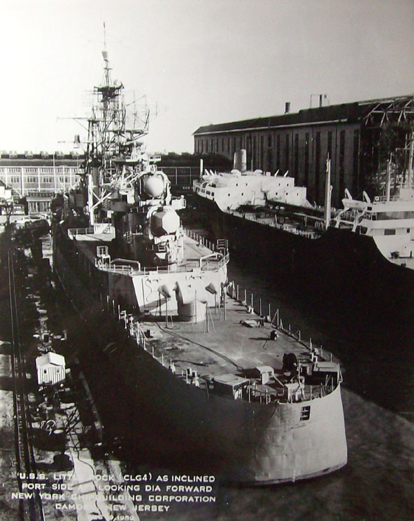 Photo 1-H Camden Shipyard ca. 1959 |
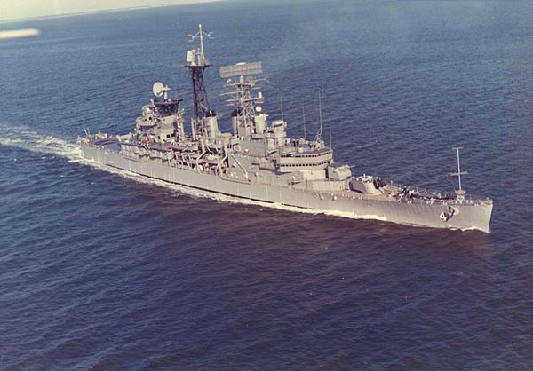 Photo 1-I Air View #1 ca. 1965 |
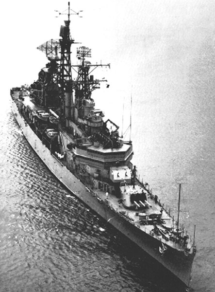 Photo 1-J Air View #2 ca. 1961 |
 Photo 1-K Underway Port Side View ca. 1961 |
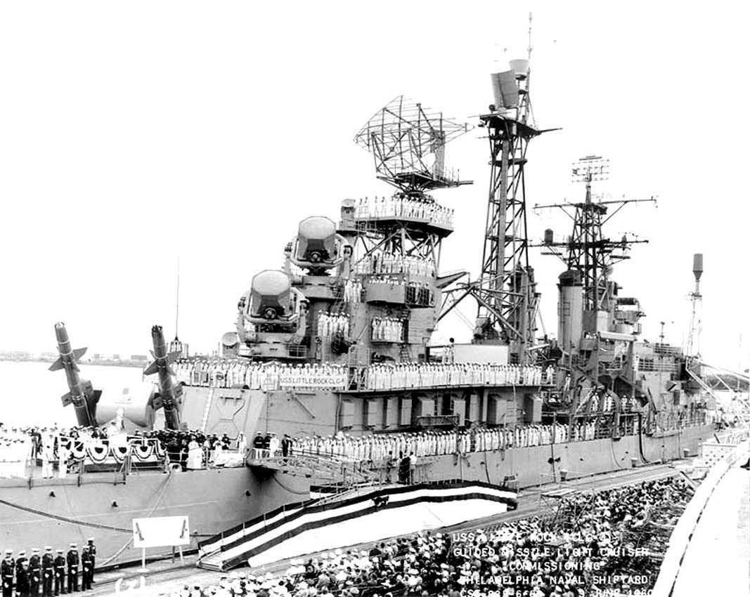 Photo 1-L Aft Starboard Quarter 1960 |
 Photo 1-M Talos Launcher 1960 |
 Photo 1-N Bow View ca. 1966 |
 Photo 1-O Underway ca. 1962 |
 Photo 1-P Underway ca. 1965 |
 Photo 1-GI CLG 4 at anchor, Gaeta, Italy |
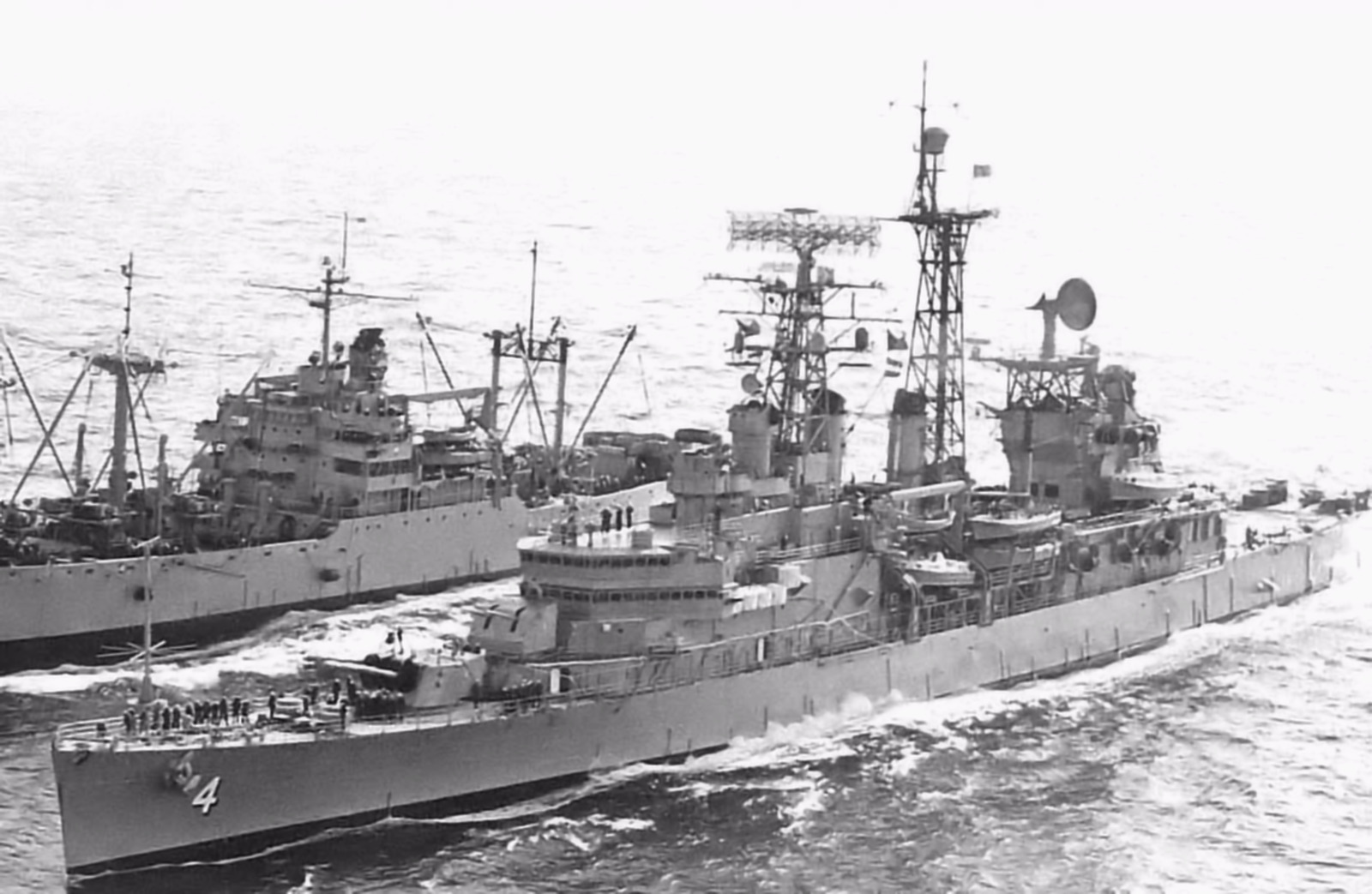 Photo 1-UR CLG 4 at sea |
||
 Photo 1-Q Underway Jan 1972 |
 Photo 1-R Underway July 1967 |
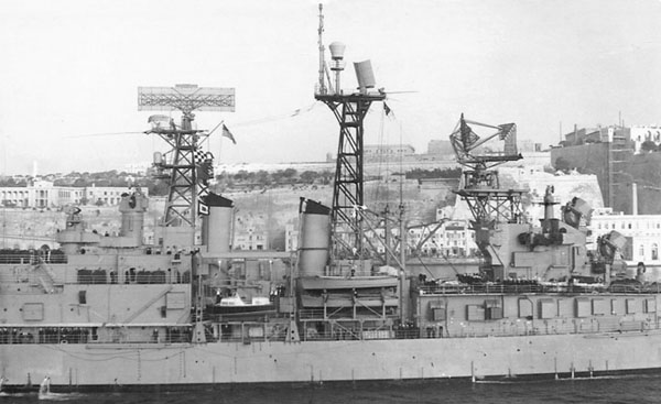 Photo 1-S Ships Boats - Portside ca. 1961 |
|
 Photo 1-TP Ships Boats - Port Side ca. 1966 |
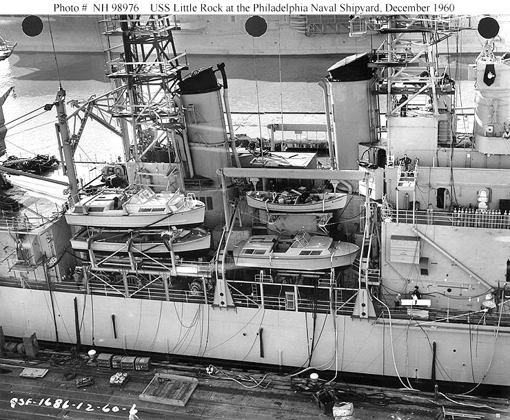 Photo 1-TS Ships Boats - Starboard Side ca. 1960 |
||
 Photo 1-U Missile Radars Stb'd View ca. 1966 |
 Photo 1-V Bridge and 04 Level ca. 1966 |
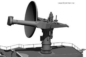
 Drawing 1-A AN/SPG-49 Radar (Copyrighted Drawing A) |
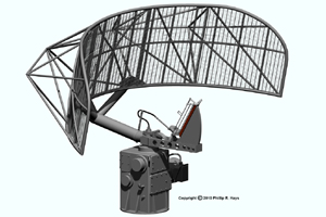
 Drawing 1-B AN/SPS-30 Search Radar (Copyrighted Drawing B) |
 Photo 1-AT Aft Tower with SPS-30 |
 Drawing 1-34 Mk 34 Gun Fire Director |
 Photo 1-MK34 (1) Mk 34 Gun Fire Director |
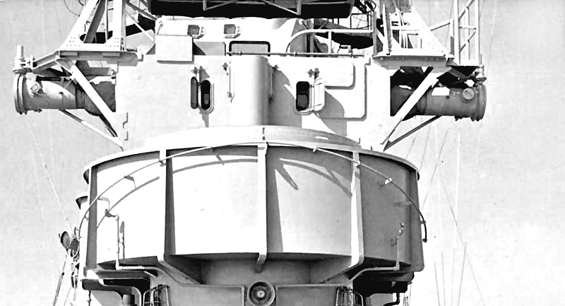 Photo 1-MK34 (2) Mk 34 Gun Fire Director |
 Drawing 1-C AN/SPS-43 Search Radar (Copyrighted Drawing C) |
 Drawing 1-D AN/SPW-2 Guidance Radar (Copyrighted Drawing D) |
 Drawing 1-E AN/SPS-10A Search Radar (Copyrighted Drawing E) |
 Drawing 1-F Mk37 Gun Fire Control Director (Copyrighted Drawing F) |
 Bow Discone Antenna |
 Drawing G Bow Detail #1 Note: For USS Little Rock models, use hull number 4 NOT hull number 5 (Copyrighted Drawing G) |
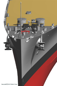 Drawing H Bow Detail #2 Note: For USS Little Rock models, use hull number 4 NOT hull number 5. (Copyrighted Drawing H) |
 Photo DM USS Little Rock Depth Markings |
 Photo 1-W Bow Detail #4 |
 Photo 1-X Bow Detail #5 |
 Photo 1-Y1 Bow Detail #6 |
 Drawing 1-J Bow Detail #7 See Dwg. DM above. (Copyrighted Drawing J) |
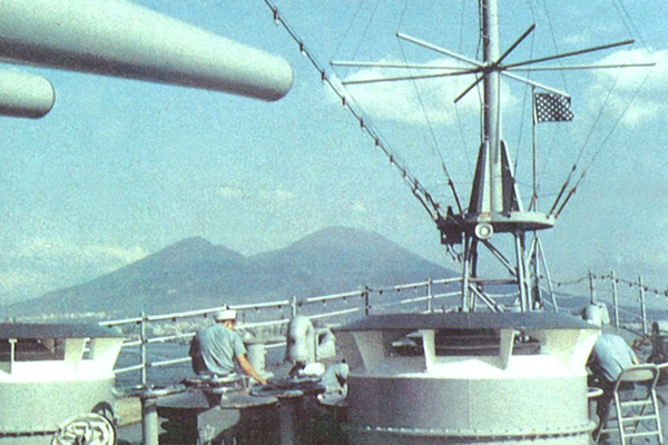 Photo 1-Y2 USS Little Rock Bow Detail #7 |
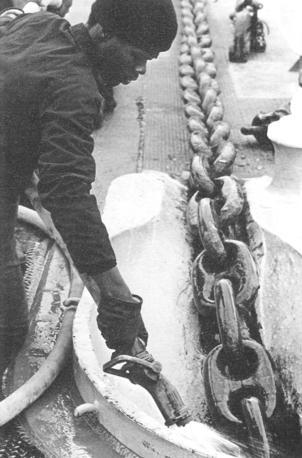 Photo 1-Y3 USS Little Rock Anchor Chain and Hawse Pipe |
 Photo 1-Y4 USS Little Rock Bow Detail #8 |
 Photo 1-Y5 USS Little Rock Flag Hoists (Port) |
 Photo 1-Z Bow Detail Deck View |
 Photo 1-Z1 Bow Detail Stem View |
 Photo 1-LS Lookout Station 04 Level Starboard Side |
 Photo 1-LP Lookout Station 04 Level Port Side |
 Drawing 1-K Hull Details Note: For USS Little Rock models, use hull number 4 NOT hull number 5. (Copyrighted Drawing K) |
 Drawing 1-L Stern Light Details See Drawing N below for location details (Copyrighted Drawing L) |
||
 Drawing 1-SD Stern Detail showing USS Little Rock aft antenna mount. Port antenna is shown. Similar mount on starboard side |
 Drawing 1-MH Detail showing starboard side and aft end of Missile House. |
||
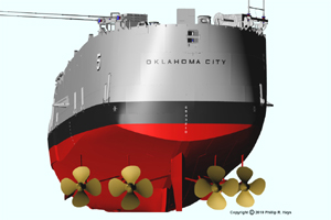
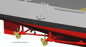 Drawing 1-M Prop Shafts, Struts and Rudder. (Stbd Side shown) (Copyrighted Drawing M) |
 Drawing 1-N Stern Details Note: For USS Little Rock models, use hull number 4 NOT hull number 5 and correct ship name. (Copyrighted Drawing N) |
||
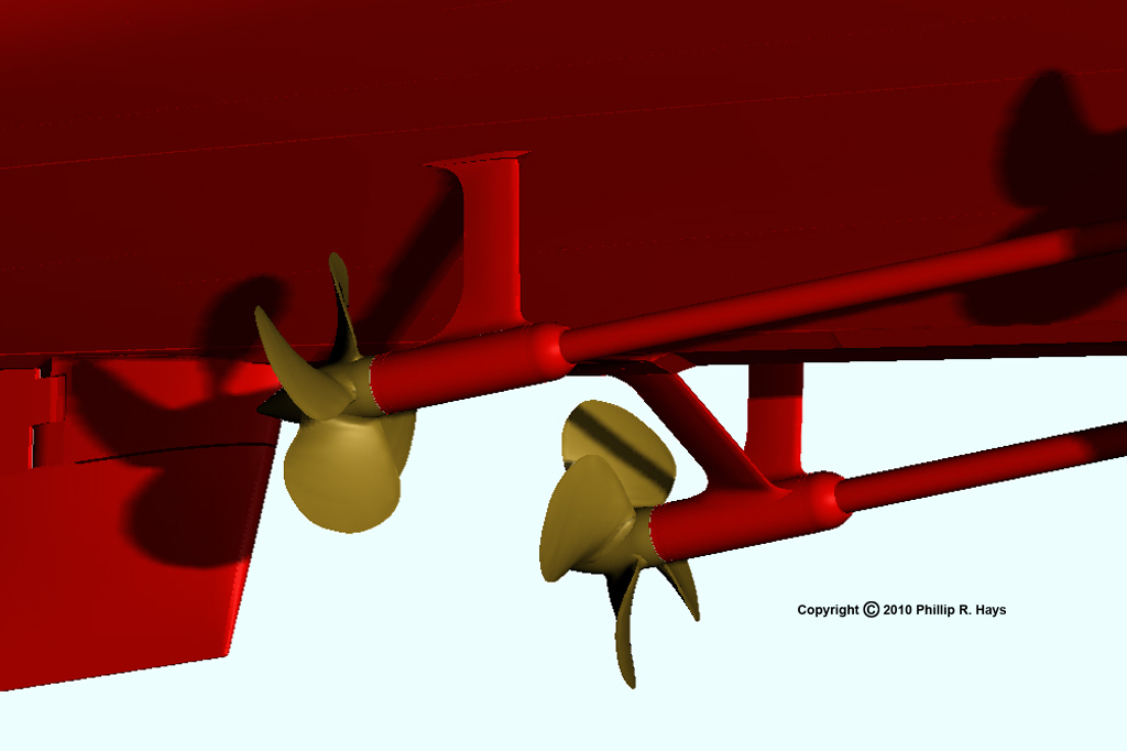 Drawing 1-O Prop Shafts, Struts and Rudder. (Close-up of Stbd Side shown) (Copyrighted Drawing O) |
 Drawing 1-P Prop Shafts, Struts and Rudder. (Bottom View) (Copyrighted Drawing P) |
||
| Notes: |
1.
All photos, unless otherwise noted, are official U.S. Navy photos and
are in the Public Domain. 2. All drawings and sketches are copyrighted and may not be used without permission. 3. All drawings unless otherwise noted have been generously furnished by Dr. Phillip R. Hays. (You can view his entire website dedicated to the USS Oklahoma City CLG5 HERE.) |
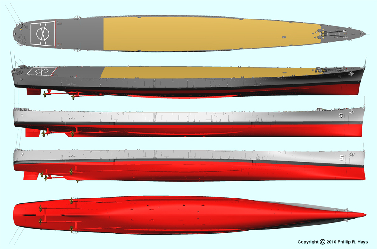
 CL 92 Hull Offsets (w/o Modifications) Click drawing to expand it. |
| CLG 4 As-Built Design Specifications |
|
| Ship Name: |
• U.S.S. Little Rock |
| Designation: |
•
CLG 4 |
| Type: |
• Guided Missile Cruiser, Light |
| Class: |
•
Galveston |
| Displacement (Standard: |
•
10,670 tons |
| Displacement: |
•
15,205 tons |
| Length at Waterline: |
•
600 ft. |
| Length Overall: |
•
610 ft |
| Beam: |
•
66 ft. |
| Height: |
•
166 ft. above keel |
| Draft: |
•
32' 10" max. |
| Propulsion: |
•
4 Babcock & Wilcox, 634 psi boilers • 4 GE geared steam turbines • 4 Screws • 100,000 hp (75 MW) |
| Speed: |
• 32.5
knots (60 km/h) |
| Complement: |
•
1,400 officers and enlisted |
| Armament: |
•
3 x 6" / 47 guns (1
triple turret) • 2 x 5" / 38 guns (1 dual mount) • 1 twin-rail Talos launcher |
| Armor: |
•
Belt: 3.25 - 5 in. • Deck: 2 in. • Turrets: 1.5 - 6 in. • Barbettes: 6 in. • Missile Magazine: 1.5 in |